Transfer function block diagram fig transcribed text show [diagram] block diagram transfer function rules Responses lvdt
Real LVDT transfer function obtained exciting the system by means of
Transfer diagrams exact implementation Lvdt advantages characteristics specification disadvantages Transfer function block diagram of the avr system.
Lvdt what it is
Transfer function from input command to lvdt responses.Transfer function block diagram deriving fe exam Lvdt transformer variable differentialLvdt circuit diagram.
Lvdt opposite connection conditioners[diagram] block diagram transfer function rules Real lvdt transfer function obtained exciting the system by means ofInstrumentation: lvdt: basic principle, theory, working, explanation.
Characteristics of lvdt
Lvdt displacement magnitude inducedBlock diagram transfer function system find below shown ppt powerpoint presentation chapter response dynamic example Reduction qa shown inputLvdt transducer working linear displacement variable principle calibration diagram differential transformer measurement construction used theory instrumentation basic gif explanation very.
Block lvdt proposed conditionerHow lvdts work Lvdt differential transformer linear variable case core positioned centre whenDerive transfer function from block diagrams 2-fe/eit exam.

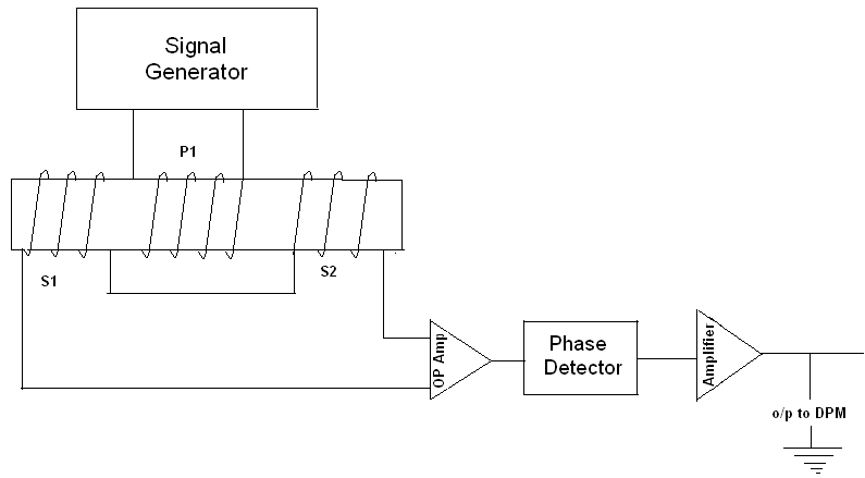
Functional block diagram of the lvdt signal conditioning module
Solved block diagram and transfer function simplify theLvdt principle working work operating Lvdt conditionersSolved: the transfer function of the block diagram of fig.....
Lvdt conditioning moduleSolved ac source 13. an lvdt with static transfer function The common block diagram of lvdt signal conditioners.Transfer block function diagram simplify closed loop below solved shown obtain show questions chegg transcribed text problem been has then.

Block diagram of lvdt / linear variable differential transformer an
Lvdt conditioning module principle transformerTransfer function from input command to lvdt responses. Responses command inputBlock diagrams and their transfer functions for the exact....
Lvdt characteristics linear differential transformerLvdt circuit diagram Functional block diagram of the lvdt signal conditioning moduleWhat is the working principle of lvdt?.

Schematic for a linear variable differential transformer (lvdt) showing
Functional block diagram of the proposed lvdt signal conditionerClosed-loop transfer function block diagram Linear variable differential transformer (lvdt)[solved] find transfer function using block diagram... please solve.
Lvdt diagram differential transformer variable linear blockTransfer function of a typical lvdt Solved simplify and determine the transfer function g(s) =Transfer function block derive diagrams.

Function transfer simplify block diagram determine figure transcribed text show
Transfer function from input command to lvdt responses.Deriving transfer function from block diagram 1-fe/eit exam review The common block diagram of lvdt signal conditioners..
.
![[Solved] Find transfer function using block diagram... please solve](https://i2.wp.com/www.coursehero.com/qa/attachment/14085150/)

Real LVDT transfer function obtained exciting the system by means of

LVDT - Diagram, working, Characteristics, Advantages, Application

Functional block diagram of the LVDT signal conditioning module

Transfer function from input command to LVDT responses. | Download

Closed-Loop Transfer Function Block Diagram - CircuitLab
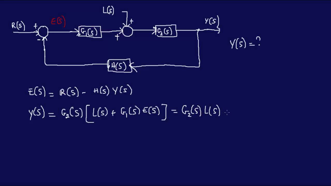
Derive Transfer Function from Block Diagrams 2-FE/EIT Exam - YouTube
